The New Challenge: Fiber Comes into the Home
The current migration of optical fibers closer to and even into the home has increased service providers interests in the new bend-optimized fibers (low-bend fibers). To verify their usability, the two most promising types, the trench-assisted and the nano-structured designs are discussed, and throughly investigated in respect of their performance and compatibility to standard single mode fibers. In particular, they were intensively tested and evaluated in terms of splicing, processing, mechanical characteristics, and optical performances. 
As a result the trench-assisted and nano-structured fibers are confirmed to be good candidates for loss and bend critical application(such as indoor wiring) because of their much higher immunity to bending losses, yet remaining to a high degree compatible
to the standard single-mode fibers.
Although optical fiber has superior signal capacity and immunity to electromagnetic interference, there is one basic aspect where fiber lags behind copper cables and this is the signal loss incurred if bent around tight corners.
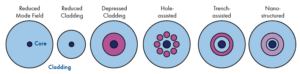
This makes optical cable installation much more cumbersome than electrical types, because they have to be installed more carefully and with large bending radii. In an attempt to reduce the bending loss of single mode fibers (SMF) several ideas have been proposed. They include (Figure 1) increasing refractive index difference between core and cladding glass while reducing the mode field diameter (MFD) [1] with/without reducing the cladding, depressing the index of the cladding near the core region [2], adding a ring of symmetric holes around the core [3][4], adding a low index trench (Fluorine doped glass ring) [5]-[7], and introducing a random void nano-structured ring [8].
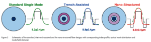
The industry has also responded to these recent innovations by offering a new standard (ITU-T G.657; portions are shown in Table 1). The G.657 standard describes two groups of bend-improved optical fiber types. The first is referred to as table A, covering single mode fibers that are fully compliant with the embedded base of the standard low-water-peak (G.652D) fibers, yet offer macro-bending loss of 0.75dB maximum for one turn with r=10mm at 1’550nm. Which is about 3 to 6 times lower bending loss than for conventional SMF at this radius. The second recommendation, G.657 table B, describes the performance of fibers with macro-bending loss of 0.5dB maximum for one turn with r=7.5mm at 1’550nm.
Fibers fulfilling G.657 table B have about 15 to 30 times lower macro-bending loss than conventional G.652D fibers at this radius. The table B recommendation encompasses bend-insensitive fibers that may not be compliant with the standard SMF such as fibers with very small mode-field diameters, with a reduced cladding, or hole-assisted fibers. Yet even performance levels of G.657 table B may not suffice for some in-residence optical applications, where full compatibility to standard SMF will be required, and where installers may wish to staple and route optical cables around sharp corners without conduit or management elements. As a consequence standardization bodies are currently discussing a new class ‘beyond table B’
for indoor applications with a macro-bending specification as low as 0.1dB/turn for a radius of 5mm at 1’550nm; about 100 times lower macro-bending loss than a standard SMF.
Among the different low-bend fiber propositions described above (Figure 1), the trench-assisted and nano-structured fiber designs are the most promising approaches due to their potential bend performance (both claim to reach performance levels of G.657B and beyond) while being compatible to the standard SMF. To verify this declaration in reality, we will concentrate in the following text on these fiber designs, execute different tests to simulate daily use, and compare them to the standard SMF.
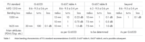
Mode field comparison: trench-assisted, nano-structured and standard SMF Reducing bending loss can normally be done by increasing the refractive index difference between core and cladding. However by doing so, it’s very difficult to maintain the mode field size and stay single mode at the same time. The trench-assisted and nano-structured approaches solve this by having the same core cladding structure in the center as the standard
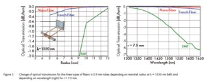
SMF, but adding a low index trench around the core (see Figure 2). Proper design of the position of this ring will only impact the tail of the optical field distribution (main part to cause optical bend loss) without seriously modifying the fundamental mode properties, such as mode field diameter, attenuation characteristics, and dispersion properties. While still being compatible with the standard G.652D range (8.6-9.5 μm), the resulting mean value of the mode sizes become slightly different (9.2 μm for the standard, 8.9 μm for the trench-assisted, and 8.6 μm for the nano-structured fiber).
However theoretical optical coupling losses (assuming Gaussian mode shape [9]) due to this mode size difference (0.3-0.6 μm) are negligible (less than 0.01 dB). So although the shape of the mode fields are not identical, the three investigated types of fibers are to a high extent comparable and the ring types have the potential to allow-bending around tight corners without noticeable increase in attenuation.
For the following tests all three types of fiber were used to manufacture 0.9 mm semi-tight tubes and 2.7 mm indoor type simplex cables.
Bending performance
Generally, bending losses of any type of fiber exponentially decrease with bending radius and increase with operating wavelength. To determine the bending performance of all three types of fibers, standardized bending loss tests (IEC 60794-1-2 E11A) were carried out on the 0.9 mm type tubes. Thereby the induced fiber attenuations on mandrels with different radii at selected wavelengths (see the results at λ=1550 nm in Figure 3 left), as well as the spectral loss for a mandrel of r = 7.5 mm (Figure 3 right) were monitored. Both low-bend fibers present a highly improved bending loss behavior compared to standard SMF and obviously fulfill the performance specification as given in G.657 table B. As the measurements showed, the trench-assisted type can be bend down to r=10mm while staying below 0.1 dB per full turn up to 1625 nm wavelength, whereas the nano-structured fiber reached the same for r = 5 mm.
These measurements clearly indicate that these two types of low-bend fibers could make fiber installations less critical, and more flexible as they allow-bending around tighter corners.
Mechanical characteristics
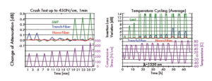
Besides maltreatment of the optical fibers due to tight bending, they are often squeezed and crushed during and after installation through staples and other supporting features and they might have to endure temperature changes. To check and compare the mechanical and environmental reliability of the different types of fibers, crush tests (according IEC 60794-1-2 E3) using the 0.9 mm tubes and temperature cycling tests (according to IEC 60794-1-2 F1) using the 2.7 mm cables were executed. Selected results are given in Figure 4.
Both low-bend fiber types (even when protected only by 0.9 mm tubes) demonstrated negligible loss increases for 1min compressive pressures up to 450 N/cm, in contrast to the standard SMF (> 0.4 dB). The temperature change test showed similar behavior as in the macro-bending test. Even under very severe cooling (–40 °C) a moderate (< 1 dB) increase in losses for the nano-structured fiber occurred (λ = 1550 nm). To some extent higher (~5 dB) losses were measured for the trench-assisted fiber.
However, both types of low-bend fibers do outperform the cable with the standard SMF, which even at –15 °C exhibits losses higher than 5 dB (this indoor cable is specified between –20 and 70 °C at λ = 1300 nm).
The measurements confirm that besides macro-bending micro-bending performance (main cause for loss during compressive stress) is also enhanced. They further allow for the assumption that the nano-structure is not damaged (collapsing/destruction of the voids) under mechanical pressure. Therefore, the use of low-bend fibers for manufacturing of optical cables, really improves the optical performance under mechanical and environmental stress.
Splicing investigations
All indoor optical communication systems have to be connected to the legacy world, which typically operates using standard SMF. Often this connection is performed by fusion splicing. However, low-bend fibers, even those compliant to G.652D may not splice seamlessly to
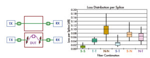
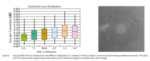
other standard SMF due to mode shape mismatch, holes or voids in the glass, or dissimilar types of glass within the fiber. To confirm the splice-ability of the investigated low-bend fiber types a systematic splicing field-test (Figure 5 left) was carried out between and across all possible fiber combinations at 1310 nm wavelength. The measured results are summarized in Figure 5 (right) using box plots, which indicate mean value(horizontal line), 75 % (box), and 98 % range (vertical line) of the acquired splice losses data (80 connections per set).
This graph illustrates quite clearly the variation in splice-ability among the three different fiber types. The highest distribution is the nano-structure fiber to itself (0.04-0.18 dB), although theoretically (same mode field size of the two splice partners) a similar distribution as with the standard SMF (0.0-0.03 dB) should be obtained. This may be explained by a sub-optimal set-up of the splicer (no core, only cladding alignment could be used), and/or a possible asymmetric collapsing of the voids during splicing. It is generally expected that by improving splicing techniques (recipes), performance levels should improve and may even approach lower loss distributions similar to standard SMF splicing.
Although there is a slightly worse splice performance with the low-bend fibers, their overall loss levels (mean < 0.1 dB, max < 0.2 dB) are well suited for indoor applications, where the higher losses are over-compensated by the potential reduction in macro bending loss.
Connectivity investigations
Connection to the outer world can, besides fusion splicing, also be achieved by optical connectors. Due to the different glass structures of the new low-bend fiber types, the question has arisen, if during the assembly process the endface will behave in a similar manner to the standard SMF and if it will match the geometrical and quality criteria’s.
The manufactured 0.9 mm tubes containing the three types of fibers were assembled with LC-PC and SC-APC connectors using standard assembly processes (not knowing what type of fiber they were using). Fortunately, during the assembly process no special care was taken nor had to be,
except for the visual inspection step, where the unfamiliar (but characteristic) endface appearance of the nano-structured fiber was noticed (see Figure 6 on the right).
Under the 400 x magnification the nano-structured region was noticeable as colored spots, whereas the trench region can barely be seen. Using white light for backside core illumination the cladding region between core and trench and between core and nano-structure becomes visible as weak light ring.
The measured endface geometries (radius, apex offset, fiber protrusion) of the fiber core were not distinguishable between the different types of fibers and they stayed well within the tolerance range given by IEC 61755-3-1/2.
To get a better view of the influence of polishing, cleaning and mating of the connectors a selection of endfaces (see Figure 7) were studied under a high resolution scanning electron microscope (SEM). Looking at the pictures it becomes clear that some more scratches and traces are visible under the SEM, due to its great resolution down into the nanometer range.
However the endfaces still look very good proving the quality of the polishing process.
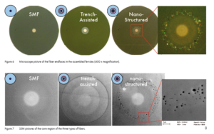
In these pictures the ring of the trench-assisted fiber becomes evident and the nano-structures can now be clearly distinguished as sub-micron holes. Despite concerns that polishing debris or other residues remain in the holes or cause more scratched surfaces, the endface looks as it should do. Closer inspection of the holes (see blow-up with higher magnification) shows that their size is in fact in the nano range (< 200 nm, compare to the 1 μm reference line at the bottom) and that they are randomly distributed.
Overall, it can be stated that despite the difference between the trench and the nano-structure, a standard assembly process can be used without restriction or adaptation (such as sealing, etc.) for both types of low-bend fibers.
To prove the compatibility of the connectorized fiber assemblies their loss distributions were investigated at λ = 1310 nm in a similar way as the splicing. Mating loss results (LC-connector side) for all possible combinations are given as box plots in Figure 8 (on the left). In contrast
to the results obtained in the spicing tests, the individual distributions resemble each other. The slightly higher mean values of the insertion loss of the low-bend fibers to the SMF (S-T and S-N to S-S) may this time be partly explained by differences in the mode shape. The higher mean loss of the low-bend fibers to itself (T-T and N-N) in respect to the SMF (S-S) again indicate that they might have slightly higher geometrical tolerances (core excentricity, fiber diameter) due to the more complicated glass structures.
Finally, to check if the nano-structures are going to suffer after a number of connections, a mating cycle test (IEC-61300-2-2) of 1000 re-connections was carried out. During the test no loss degradation was noticed. Although the endface had slightly suffered (more scratches, Figure 8 right) and there were some contaminations (not cleaned properly), the nano-structured fiber behaved similar to the standard SMF.
Overall, despite the slightly higher mean values (0.11dB instead of 0.07dB), it can be stated that the connector performance is compatible to standard SMF and is well suited for indoor applications.
Reliability considerations
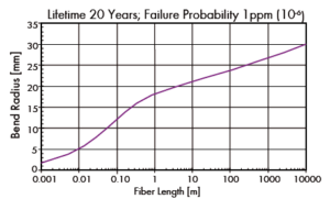
So far we’ve only seen the benefits of using low-bend fiber for optical cable installations. However, signal transmission reliability of an installed optical link must be viewed in terms of both optical loss and mechanical stability. With traditional rules for fiber management at large bend radii, fiber breakage has not been an issue. However, as fiber bend radii drop, fiber lifetime becomes an important consideration. Just take into account, that the stress onthe fiber at 5mm bend radius is 4 times higher than at 10 mm bend radius and more than 40 times higher than on a fiber following the traditional 30 mm bend radius.
The formulae to estimate the reliability of a fiber under a constant service stress (based on a power law for crack growth) has been defined in the standard IEC 62048. Due to the same stress distribution across the fiber diameter, no physical reason for another lifetime rule among the different fiber types is to be expected. By applying this formula the allowed length of fiber that reaches a lifetime of 20 years with a failure probability of 1ppm depending on the bend radius was calculated (see Figure 9).
Although there is a slightly worse splice performance with the low-bend fibers, their overall loss levels (mean < 0.1 dB, max. < 0.2 dB) are well suited for indoor applications, where the higher losses are over-compensated by the potential reduction in macro bending loss. As a result it was found, that to reach such reliability levels (20 y, 1 ppm) only 5 cm of fibers can be bent with a radius of 10 mm (not even a full turn) and only 1 cm with a radius of 5 mm (a little more than ¼ turn), in contrast to the several 1000 m in distribution frames (with splice cassettes limiting fiber bend radius to 30 mm). Consequently, tight bending of any type of fibers reduces link reliability per turn significantly, and the question arises what risk levels (how
many sharp bends) are acceptable for the customers.
We propose to use trench-assisted and nano-structured fiber types for bend and loss critical applications. However to keep the system reliable, we advise that the installation of low-bend fibers are treated with the same attention as for standard single mode fibers and that proper fiber management should be used.
Conclusion
The new trench-assisted and nano-structured bend resistant fibers types have been extensively tested and compared in respect of the optical properties of standard single mode fibers. They have shown better performances under bending, mechanical and environmental conditions, as well as to some extent their compatibility to standard SMF. Normal manufacturing processes can be used to assemble connectors with these fibers while reaching almost similar optical performances.
Splicing of these fibers on the other hand is more critical, resulting in slightly reduced performance levels, which may be overcome with further splice and manufacturing process improvements. Despite the better bending performance and the big advantage in loss and bend critical application, lifetime reliability under very tight bending conditions still needs to be considered. Trench-assisted and nano-structured fibers are recommended for bend and loss critical applications as they are a real advance to current standard single mode fibers, but they should be handled with similar care as all optical glass fibers.
Note: For all of the above described investigations we used for standard SMF: SMF28® of Corning®, for trench-assisted fiber: BendBrightXS® of Draka®, for the nano-structured design:
ClearCurve® of Corning®, for 0.9 mm tubes: CW-E9 of HUBER+SUHNER®, and for 2.7 mm cables: CWJH-H27 of HUBER+SUHNER®.


.png)


 7
7